- Shear and Moment Diagrams
- Statically determinate beams and frames
- Double Integral Method
- Moment Area method
- Statically Indeterminate beams and frames
- Force Method
- Slope/Deflection Method
- Indeterminate Shear/Moment
- Matrix Analysis
Shear and Moment Diagrams(statically determinate)
I've covered the basics in the statics section of my web page. So, I'll go into depth with my analysis of shear and moment diagrams. I'll try to use more complicated loading conditions and I'll introduce hinges. Lets start with a simply supported beam:

- The simply supported beam above is subjected to a evenly distributed load from L/2 to L. Both ends are pinned so there can be no moment at either end.
- To find the reactions, we place a statically equivalent load in the middle and sum the forces and moments about on of the support locations and calculate Ra and Rb.
- Now that we have Ra, we know the shear force from support A to L/2. At L/2 we know the shear force must change linearly as the evenly distributed load acts form L/2 to L. We find the slope of the shear by subtracting Ra from Rb and dividing by the acting length (L/2)
- The first half of the moment diagram is a slam dunk. Just like the evenly distributed load affected the right side of the shear/moment diagram, we can use the same concept on the moment diagram. it increases linearly from 0 to L/2 with a maximum value equivalent to the area of the shear diagram.
- The point of inflection of the the moment diagram (slope = 0 = flat) is where the shear force = 0. To find the Maximum moment, add the shear force at L/2 to the area of the shear triangle from L/2 to the location of zero shear (5L/8) discovered from the third bullet.
- From 5L/8 to L, we know the moment must decrease non-linearly (2nd power). Who cares what it looks like.
Another example worked out in metric with the addition of a hinge. A hinge is an internal reaction that doesn't allow moments and can only transfer shear force (summing moments about a hinge = 0, hinges also allow for one extra equation).

Here is another example, except there is a cantilevered end at the end of the simple support and a concentrated moment.

For my last Shear and Moment diagram example, I'll look at a frame. A frame is a structure that has ridigidly connected members that allow for moments to be transferred. Don't be frightened by a frame, it behaves much like a beam, in that, it is a series of beams.
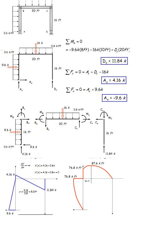
- The Frame example isn't complete, but here you can get the gist of the analysis.
- Solve for the support reactions
- Work your way from one member to another, distributing the moment from one beam's end to the beginning of the attached beam.
- Draw each beams shear and moment diagram accordingly to attain the transferred moments and shears.
Deflections of Statically determinate structures
There are a ton of ways to calculate deflections for determinate structures. I've highlighted the double integration method in the strength of materials section as well as the moment area method. Honestly, double integration is the most annoying thing to preform as one has to continually solve for integration constants using boundary conditions, but to be thorough, I'll include another example of double integration:

Lets look at my favorite method again, the Moment Area method. Here are all the basics:


Statically Indeterminate Structures
Well, everything we've talked about so far has been structures in which we have enough equations (three + how ever many hinges are present) to solve for all the internal forces and external reactions. A statically indeterminate structure is a structure that has more unknown reactions that can be discovered using the equations of statics (summing forces and moments). In the indeterminate case, we must use the member properties (E, I, L) to find reactions.
Force Method
Lets look at the first and easiest method, the Force Method. Basically, the force method is determine an unknown reaction by calculating the force that would be necessary to bring a displacement back to equilibrium. First I'll show you an example:

So, this is a pretty simple and handy way to calculate redundant reactions. However, it gets ridiculously tedious for many degrees of indeterminacy. This is why we have other methods. The force method, however is the basis for calculating member stiffnesses for more advanced methods of structural analysis.
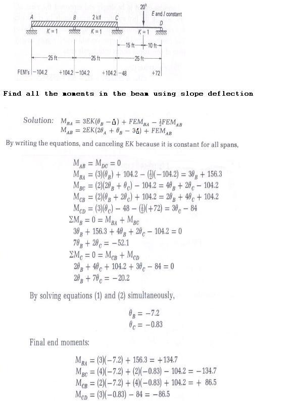
Slope/Deflection Method
Before I get into the weeds about what the slope deflection method is, I need to explain what a fixed end moment is. A fixed end moment (FEM) is the moment caused by a load on a beam with both ends fixed (a beam cantilevered at both ends). The reason the FEM is so important is because it is the base point from which we add or subtract moments to find the actual end moments (don't let this confuse you, just use the equations and it will work out. Now, to find the FEM for a member, just look at the following equations and plug in the same values give to you in a problem:

The slope deflection method is the basis for establishing member stiffnesses. Any beam has a stiffness based off its length, moment of inertia, and modulus of elasticity. I won't go through the derivation because you probably don't care. However you should know that a member can be subject to end rotations and translations (perpendicular to the beams major axis), each end rotation and translation is associated with a member stiffness the resists the impending force. This is what slope/deflection is based off. Here is are the two governing equations and the procedure for analyzing any structure (not that theta A and theta B are the left and right rotations, respectively):

Here is a basic example of a beam to get you started on the slope deflection method, note that K is used instead of the stiffness coefficient (it doesn't really matter, if E and I are the same for each span they will cancel anyways):
Indeterminate Shear/Moment Diagrams
The shear/moment diagrams for indeterminate structures function the same as determinate structures. In most cases you will know the end forces for a section of a beam or frame. This causes no problem, you will know the external loading and with the member forces you can draw the diagrams. Lets take a look at a highly indeterminate beam:

- The above example is a beam in which we know all the intermediate span end forces. Given that there is an evenly distributed force along the length of the span we can draw the approximate parabolic moment diagrams for each beam.
- So, after you have analyzed all the forces using some Structural Analysis Method, all you have to do is be a good bookkeeper to draw the shear and moment diagrams.
Matrix Analysis
Matrix analysis is as far as you can take traditional Structural Analysis, that is, to analyze each member individually and compute all the internal, external, or end forced. The next level would be finite element analysis, which breaks down the matrix member analysis to the element (small element) size.
So, what are the building blocks for Matrix Structural analysis? Well, what we want to do, ultimately, is find an easy of logging member stiffness based of known values (E,G,L,A,I,J). We also want to find a way to describe element forces (that is, the forces acting on an individual member) and input them into a larger matrix that outputs all the desired displacements or forces.
Here are a few basics I have outlined to help you get a fundamental understanding of what is going:

Once all the elemental stiffnesses have been assembled they are then transformed to the global coordinate system and compiled into the structure stiffness matrix. The structure stiffness matrix includes all elements and may also have additional degrees of freedom such as torsion, rigid lengths, etc. The structure stiffness matrix may also be condensed (for instance, neglect axial deformations) or partitioned as the user requests.
Conclusion
I've introduced you to some major concepts and given you a few worked examples to help you understand deflections and structural reactions. There may be some additions to be made (Moment distribution method, continuation of matrix analysis, etc.), but I hope what I have given you is helpful and interesting. Feel free to email me any questions.