This section is an advancement of statics. Mechanics of materials applies the same equations and statics, except that the bodies are now deformable. What does this mean? It means that we will have to analyze problems using stress/strain relationships.
So, what is stress? Well, it is a force over an area. The same as atmospheric pressure or any other pressure (except peer pressure). Here is a bar under some axial loading:


Of course the magnitude and direction (sign, +/-) may change, but the concept is the same, Stress = P/A. I'll define Compressional stress as a stress that shortens an element (squishes) and tensional stress as one that would elongate an element.
What kind of an effect do axial and shear stresses have on material?


Where stain is the change in length over the original length. So, for an elastic material (one that doesn't permanently deform and that he stress and strain are related by Hooke's law[stress = Elasticity modulus * strain]) the change in length and the stress have a linear relationship (for reasonable stresses). We denote this relationship with the Modulus of Elasticity (E), for steel it is 29000 Kips/in^2. OK, here is the formula for bar elongation of a bar under axial loads:

Beam Theory!
Cool, now lets look at something that is actually interesting: Beam Theory. A beam is something that is long and slender, it loaded perpendicular to its long axis (it can also be loaded axially). We'll analyze how a beam reacts to external forces and how the internal forces cause deformations. This is why shear and moment diagrams are so important. This page is intended for Engineering students so we won't toil over the boring proofs, we'll stick to what matters and the general concepts. Lets examine a beam under some loading condition:

- We notice that the beam is bent in some parabolic shape that has a radius and a deflection below its original position. But, what is causing the deformation. Well, we we concluded that only bending moments contribute to the bending of the member (a good assumptions shear forces usually only contribute 3-5% of total deformations) we notice the following:

- The bending moment rotates the section. OK, now look at the top of the beam; we see that is has compressed and that the bottom has elongated. This means the top and bottom are experiencing compressive and tensile stresses, respectively. For a linear stress/strain material, the bending stress distribution must also be linear. Look at the top two examples in the following pic. The bottom picture shows combined bending (bending about both axis).

- The point of zero bending stress in the neutral axis and the points of maximum bending stress are the beams extremes. The formula for the distribution of bending stress is:

Bending stress is not the only stress that a beam experiences when loaded, there is also a shear stress assumed by the beam cross section. This stress is weird, the proof behind it is tedious and I don't want to do it. Here are the basics:

- There is a big difference in Bending stress and shear stress. The shear stress in a material varies parabolically and reaches a maximum at the neutral axis. This phenomenon related to shear flow. The General formula is:
- S= shear stress, Q= the moment about the neutral axis of the area above the point you want to calculate the shear stress, I = moment of inertia, b= width of desired section.
- Here is Q, find the area of the shaded region and multiply it by the centroid distance. b is .35".


- Here is the shear stress distribution on an I beam
- the equation for shear stress near the fillet of the cross section is not accurate.

Beam Deflection
This is really just a preview to what happens in Structural Analysis. Here we are not concerned about the stresses in a beam, rather the deflection of a beam along its length. The governing equation of beam deflection is:

- Where M is the complete equation for the moment distribution along a beam

For really simply loading cases you can simply use the following equations (note that for combined conditions the deflections and angles may be added to find the desired values):

Buckling


Buckling is one of my favorite topics, it is the theory of beam response due to large axial loads. For long and skinny beams, a huge load may force a beam to bend perpendicular to the axial loading axis rather than simply compress. Buckling is dependent on the cross sectional properties, length, elasticity, loading and end (fixity) conditions. This is the general buckling formula (maximum axial load) in which you can substitute different effective lengths (length between mathematical inflection points) based on the column's end conditions:


Mohr's Circle
For combined stresses in a material the maximum stress and angle the stress is acting can be computed. This is done using Mohr's Circle.

For a piece of material, the above circle governs the principle stresses, that is, the extreme stresses in the material. the circle also governs shear and normal stresses at any angle in the material. Here are the equations you need to know:

Torsion
The easiest way to explain torsion is that when you twist a member, such as a drive shaft, the member must resist the torque applied. The member's resistance has to result in some deformation, this is torsion. Take a look at the simplest case, torsion of a circular bar or hollow circular bar:

- T is the torque applied to the bar (torque is just a moment applied along the center axis of the bar). ϕ is the the angle of twist (angle of deformation). C is the radius.
- Torsion is different than normal deformation (even though it still behaves linearly for reasonable, forces), in that, it is dependent of the shear modulus G. G represents the resistance of material planes to slide past one another, G is usually much smaller than E.


- Equation one is the shear stress at any radius inside the bar.
- Equation two is the angle of twist (ϕ) at any length (l) along the bar's length.
- Equation three is the polar moment of inertia for a solid cylinder.
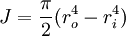
- Equation four is the polar moment of inertia for a hollow shaft.
Torsion of non circular bars is extremely complicated, take a look at the deformed shape of an I-Beam:
We can see that there are many factors involved with this situation, the polar moment of inertia is some combination of the moment of inertia about both axises (x and y), there is warping, and geometrical change. To keep things simple in the analysis we say the torsional resistance to deformation is:

Here are the torsional stiffnesses of an equilateral triangular shaft and a square shaft (found experimentally) for small deflections:

Conclusion
You've seen the basics of Mechanics of Materials here. Mechanics of Materials is, really, the first introduction to deformations of solids. It introduces the fundamental principals of stress and strain as a function of external loading.
Solid Mechanics extends much further, however. More advanced topics in Solid Mechanics include Vibration Theory, Contact Mechanics, Continuum Mechanics of solids, Finite Element Methods for solids, Stress Waves in solids, Response to Blast and Loading, the list goes on. The techniques employed with these methods involve higher level mathematics and numerical methods, so if these interest you, brush up on calculus of multiple variables, tensor notation, linear/non-linear algebra and partial differential equations!
I hope you've enjoyed my 'short' on Mechanics of Materials!