
- This equation represents the equilibrium that must exist between internal forces and external forces for a non moving object.

Lets apply this principle to a truss. But first, what is a truss? A truss is a structure that is assumed to have no moment reactions at any joint. This means that each member can only have axial forces. There are two methods used to solve trusses, the first method is the method of joints. This method involved summing the forces in the x and y direction for every joint in the system. Take a look at this example:

Lets move on to the method of sections. The theory behind this method is that if you sum moments about any part of the structure, the moments must sum to zero. This method is handy if you simply want to find one internal force, he is another example of the same truss:

Beam Statics
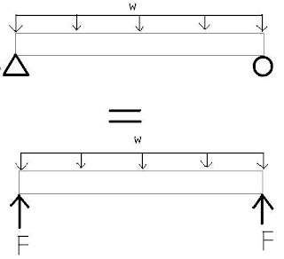
To keep things simple I'll represent the relationship between internal forces and external forces with a picture and explain what it means in the context of the static equilibrium equation. For a beam with external loading:
From the three equations of equilibrium, we have:

Lets look at a loaded beam:


Lets move on to the method of sections. The theory behind this method is that if you sum moments about any part of the structure, the moments must sum to zero. This method is handy if you simply want to find one internal force, he is another example of the same truss:

Beam Statics
To keep things simple I'll represent the relationship between internal forces and external forces with a picture and explain what it means in the context of the static equilibrium equation. For a beam with external loading:

- W is simply the distributed load (force) acting on the beam and the triangle and circle represent a pin and a roller, respectively. Technically a pin can have a force reaction in the X (horizontal) direction, bit I'm only trying to convey the internal forces of them beam at this point.

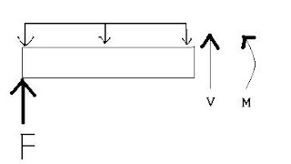
- From the same beam as before we cut a demonstrative cross-section to illuminate what the hell is going on. We still have a distributed load acting on the beam and a reaction force from the left support. However, we have the additional two forces acting (the internal forces). The forces are an internal reaction force (V, which you can visualize as another reaction force; it is simply in the beam instead of an external force) and an internal torque or Moment (M). These forces are what maintains equilibrium in the beam along it's length. The moment is always confusing, but look at it like this: it is a force time a distance that attempts to rotate the beam into equilibrium.
From the three equations of equilibrium, we have:
- These equations govern what is going on in the beam. All moments, internal, and external forces must equal zero throughout the extents of the beam.
Lets look at a loaded beam:

- Here we see a simply supported (two point forces at the ends) beam with a point force mid span. Below the beam is the shear diagram and under that is the moment diagram.
- Lets walk through this:
- The Shear Diagram
- Since the beam is loaded directly in the middle, each reaction at the ends of the beam must be F/2. As we travel from left to right, nothing changes because there in no loading to induce change. When we reach the middle the force (F) "knocks" the shear diagram by the magnitude of F (or, the sum of both reactions). As we travel right, nothing changes as the loading stays the same. However, when we reach point C, the reaction "knocks up" (sorry for the profanity) the shear diagram by F/2 to reach zero. The shear diagram of a simply supported beam bust be zero at one extent.
- The Moment diagram
- One cool way to look at the moment diagram at this stage in our learning is tho thing of it as the integral of the shear diagram. That is:
- This meant that the slope of the moment diagram is the shear force and that the area of the shear graph is the Magnitude of the moment at any point. Check it out:


- Units
- The units for Shear and Simply supported reactions Reactions are the same, (Kips, lb, N, etc)
- The units for moment are (force*Distance)=(kip*ft, N*meter, etc)

- A cantilevered beam is different from a simple support in that it the restrains the end. The restraint doesn't allow for "rotation" of the end, meaning that there is a larger (maximum) moment at the only beam restraint (as the other end is free).
- Above are the shear and moment diagrams for the beam, notice that F and Rb are the same as the loading condition doesn't change until the extent of the beam.
- The moment diagram differs significantly from the simply supported beam, in that, the maximum moment occurs at the beam/wall connection and decreases (or increases depending on your sign convention) to zero where the beam ends (remember that a moment is a function of length and an applied force).
Lets go back to the simply supported beam for a second, now lets look at a uniform distributed load. A uniform distributed load is a load that has a constant magnitude across the length of the member. Here is an example:

- As described above, the load is a magnitude W across the length of the beam. What does this mean?
- The shear force will have to change. The reaction at the end is of magnitude WL/2, and the shear constantly changes (decreases) as the distributed load constantly acts down on the beam. For a non-varying load, the shear force will vary linearly.
- Remember, the moment at any point in the beam must equal the slope of the shear diagram and the magnitude must be equal to the composite area of the shear diagram from one extreme of the beam to the point of desired moment magnitude. So, if you wanted to find the moment at x=.75L, just find the area of the left triangle on the shear diagram and subtract the area of 1/2 the horizontal distance of the second triangle (not 1/2 the area of the second triangle).
The Centroid or Neutral axis (2d shape) is the distance from a datum that the area moments of and object are balanced. In other words, the place where the areas of an object are balanced. Here is the formula to calculate the neutral axis of a 2d object:

Where Ci is the distance from the datum (I usually choose the bottom of the object) to the center point of an object. Ai is simply the area of the object.
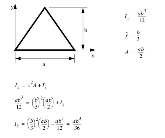
Now lets look at Moment of Inertia. The moment of inertia is a distribution of a cross section's area. It is used to calculate stresses and deflections in later topics. There are two parts of the moment of inertia from the parallel axis theorem. Here is the equation:

- Here is an example, it will explain the process much better that I can: (x is the location of the neutral axis)

This table should give you everything you'll need to calculate the moment of inertia for a given geometry:

Summary
So, we've covered everything you need to prepare you for Mechanics of Materials. We've looked at how to sum forces, shear and moment diagrams, Neutral axis/centroid and the movement of inertia. If there is anything else needed to be covered (truss, vector stuff, etc.) shoot me an email or comment on my main page.